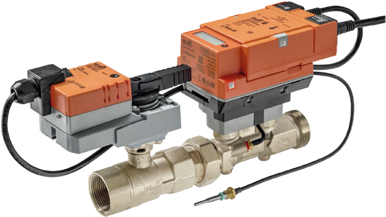
Belimo Energy Valve V4 Modbus TCP
Content languageEnglish
Description
Why the Belimo Energy Valve? Modern Heating & Cooling systems, especially in the commercial sector are often complex and require a transparent monitoring so that the possible energy savings could be reached in practice. The Belimo Energy Valve™ is in this regard a perfect tool to create transparency and sustainable correct operation of the Heating and/or Cooling System. Flexible Installation in nearly every position to any type of Heating/Cooling System such as:
- [Central] Boiler monitoring e.g. Heatpumps, Gas, Oil, Biomass - [Distribution] Systems e.g. in basement strings to the consumers - [Consumers] Replaces unintelligent on/off valves, heat meters and sensors in the central manifold of the technical room to supply e.g. Air handling units, Heat exchangers, Radiators, Fan coils or Surface-laid systems such as underfloor heating
The Energy Valve V4 is available from Pipe Size DN15 (1/2") to DN50 (2") as 2 Way valve or 3 Way Valve. The Energy Valve V4 is also available in three different versions: MID, BAC and KBAC.
- [MID] With an "accurate" Meter that fullfills the requirements of the [MID] "Measurement Instruments Directive". - [BAC] Here the MID certification is not fulfilled. - [KBAC] Here the MID certification is not fulfilled, the actuator is equipped with an emergency setting function (spring return) for e.g. power failures in the Power Grid.
The choice of paring Belimo Energy Valve with Loxone offers the possibility of:
- [Demand based Heating and Cooling]: The Energy Valve regulates depending on the Room Heating or Cooling requirement, Heating Curve, Presence detection, Window status, Automatic Shading, Weather Forecast and Energy Management (PV Surplus, Variable Electricity Tariffs, Load Management). - [Flow/Power/Energy Monitoring and Analysis]: The integrated Water Flow / Power / Heating & Cooling consumption recording of the Energy Valve ensures transparent Energy Flow Monitoring with individually created System Schematics. Using the Energy Flow Monitor for thermal outputs provides an overview of total and current energies. Energy leaks in the building can be found quickly. The valves that do not close tightly or, for example, consumers that are in “manual mode” are discovered. Using and storing statistics, creating individual notifications. e.g. threshold value excesses or error notifications. - [Automatic Hydraulic Balancing]: In the central heating & cooling system or in the lines to the consumers under all operating conditions (full load and partial load). Heating and cooling loads can be optimally supplied thanks to the simple and demand-based control. Thanks to the delta-T Optimization function of the Energy Valve, water volume flows can be reduced to the minimum and Pump Energy can therefore be saved. By using an Energy Valve, pumps can be made smaller, balancing valves, control drives and heat meters can be replaced by a product, the Energy Valve! This reduces the project costs. Differential pressure fluctuations in the network are compensated electronically. - [Application in a hybrid system]: The possibility of application in a Hybrid system or in a system that uses different Energy sources ensures cost independence, a high level of comfort and flexibility in heating and cooling. Facilitates the combination of complex Hydraulics such as multiple base-load heat generators (e.g. Heatpump or Biomass) with Peak-Load Heat Sources (e.g. Oil or Gas). - [Continuous Glycol monitoring]: Manual measurements are replaced. If the amount of Glycol is too low, there is a risk of freezing or water damage. If the proportion is too high, the energy consumption of the circulation pump increases. The Glycol concentration can be tracked in the statistics, individual thresholds can be set for notifications or automatic dosing can be carried out. - [Dewpoint monitoring]: With the more accurate and responsive Flow sensor of the Belimo Energy Valve™, systems can detect and shut off water flows before condensate forms on the chilled beams. The minimum flow temperature can be calculated using a formula building block and controlled with the EPIV valve based on the room temperatures and room humidity. - [Cost Saving]: Fast commissioning via Belimo Assistant and fast error finding thanks to Belimo and Loxone Diagnose Tools.
Structure:
Inputs and outputs · 99
| Name | Type | Unit |
|---|---|---|
| Actuator type | Modbus | <v> |
| Relative position | Modbus | % |
| Absolute position | Modbus | ° |
| Relative volumetric flow | Modbus | % |
| Absolute volumetric flow in selected unit | Modbus | l/h |
| Setpoint analog | Modbus | % |
| Temperature 1 in degree Celsius | Modbus | °C |
| Temperature 1 in degree Fahrenheit | Modbus | °F |
| Temperature 2 in degree Celsius | Modbus | °C |
| Temperature 2 in degree Fahrenheit | Modbus | °F |
| DeltaT_K | Modbus | K |
| DeltaT_F | Modbus | °F |
| Glycol concentration | Modbus | % |
| Relative power | Modbus | % |
| Series Number 1st part | Modbus | <v> |
| Series Number 2nd part | Modbus | <v> |
| Series Number 4th part | Modbus | <v> |
| Firmware version | Modbus | <v> |
| Error state | Modbus | <v> |
| DeltaT Manager Status | Modbus | <v> |
| Absolute volumetric flow in liter per second | Modbus | l/s |
| Absolute volumetric flow in gpm | Modbus | gpm |
| Setpoint flow in selected unit | Modbus | l/h |
| Absolute Power Cooling in selected unit | Modbus | kW |
| Absolute Power Cooling in kW | Modbus | kW |
| Absolute Power Cooling in kBtu per hour | Modbus | kBtu/h |
| Energy Cooling in selected unit | Modbus | kWh |
| Energy Cooling in kWh | Modbus | kWh |
| Energy Cooling in kBtu | Modbus | kBtu |
| Energy Heating in selected unit | Modbus | kWh |
| Energy Heating in kWh | Modbus | kWh |
| Energy Heating in kBtu | Modbus | kBtu |
| Nominal volumetric flow in selected unit | Modbus | l/h |
| Nominal volumetric flow in liter per second | Modbus | l/s |
| Nominal volumetric flow in gpm | Modbus | gpm |
| Nominal power in selected unit | Modbus | kW |
| Nominal power in kW | Modbus | kW |
| Nominal power in kBtu per hour | Modbus | kBtu/h |
| Setpoint flow in liter per second | Modbus | l/s |
| Setpoint flow in gpm | Modbus | gpm |
| Absolute Power Heating in kW | Modbus | kW |
| Absolute Power Heating in kBtu per hour | Modbus | kbtu/h |
| Absolute Power Heating in selected unit | Modbus | kW |
| Sensor Serial Number 1st Part | Modbus | <v> |
| Sensor Serial Number 2nd Part | Modbus | <v> |
| Sensor value 1 | Modbus | <v.1> |
| Sensor 1 value in degree Celcius | Modbus | °C |
| Sensor 1 value in degree Fahrenheit | Modbus | °F |
| Total volume in cubic meter | Modbus | m3 |
| Total volume in gallon | Modbus | gal |
| Total volume in selected unit | Modbus | m3 |
| Bus termination | Modbus | <v> |
| Absolute differential water pressure in selected unit | Modbus | bar |
| Relative water differential pressure | Modbus | % |
| Absolute differential water pressure in psi | Modbus | psi |
| Absolute differential water pressure in kPa | Modbus | kPa |
| Status of the differential water pressure sensor | Modbus | <v> |
| Differential water pressure control status | Modbus | <v> |
| Nominal differential water pressure in selected unit | Modbus | bar |
| Nominal differential water pressure in psi | Modbus | psi |
| Nominal differential water pressure in kPa | Modbus | kPa |
| Malfunction and service information | Modbus | <v> |
| Setpoint | Modbus | % |
| Override control | Modbus | <v> |
| Vmax in percent of Vnom | Modbus | % |
| Pmax in percent of Pnom | Modbus | % |
| Delta T Limitation | Modbus | <v> |
| Setpoint DeltaT in K | Modbus | K |
| Setpoint DeltaT in F | Modbus | °F |
| Control Mode | Modbus | <v> |
| Unit Selection Flow | Modbus | <v> |
| Unit Selection Power | Modbus | <v> |
| Unit Selection Energy | Modbus | <v> |
| Setpoint Source | Modbus | <v> |
| Absolute Vmax in liter per second | Modbus | l/s |
| Absolute Vmax in gpm | Modbus | gpm |
| Absolute Pmax in kW | Modbus | kW |
| Absolute Pmax in kBtu per hour | Modbus | kBtu/h |
| Vmin in percent of Vmax | Modbus | % |
| Absolute Vmax in selected unit | Modbus | l/h |
| Absolute Vmin in liter per second | Modbus | l/s |
| Absolute Vmin in gpm | Modbus | gpm |
| Absolute Vmin in selected unit | Modbus | l/h |
| Absolute Pmax in selected unit | Modbus | kW |
| Unit Selection Volume | Modbus | <v> |
| Select Meter Register | Modbus | <v> |
| Command | Modbus | <v> |
| Setpoint Flow at DeltaT in liter per second | Modbus | l/s |
| Setpoint Flow at DeltaT in gpm | Modbus | gpm |
| Setpoint Flow at DeltaT in selected unit | Modbus | l/h |
| Communication Watchdog | Modbus | <v> |
| Sensor 1 Type | Modbus | <v> |
| Sensor 1 Passive Sensor Type | Modbus | <v> |
| Unit selection pressure difference | Modbus | <v> |
| Absolute differential water pressure setpoint in selected unit | Modbus | bar |
| Absolute differential water pressure setpoint in psi | Modbus | psi |
| Absolute differential water pressure setpoint in kPa | Modbus | kPa |
| Bus watchdog fail action | Modbus | <v> |
| Timeout for bus watchdog | Modbus | s |
Ratings and comments
No ratings or comments yet.
Log in to rate, comment or ask a question. Log in